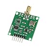
AD9833 DDS信号発生器 を追加
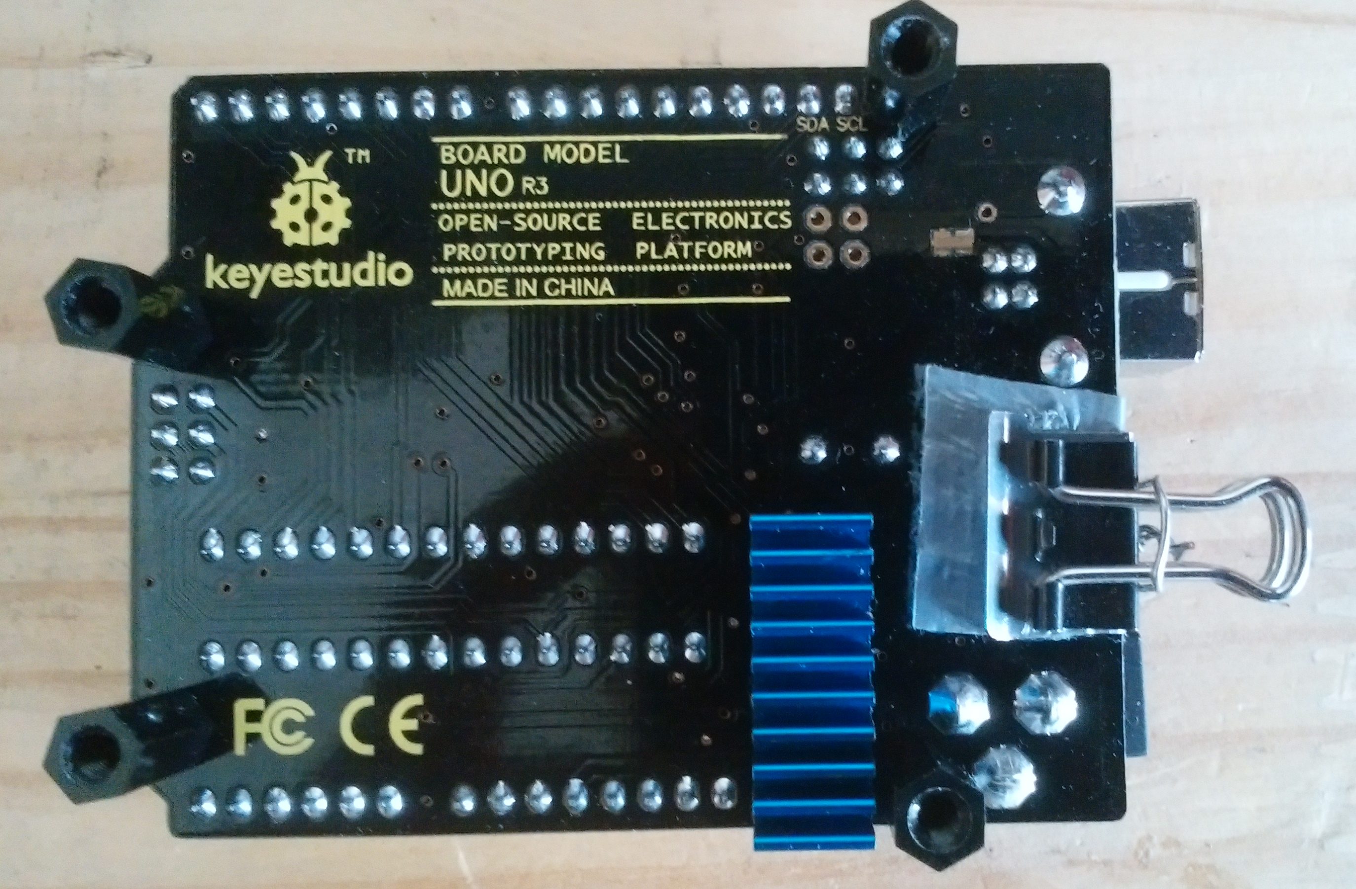
先に作成したSi5351Aクロックジェネレータを載せたシールドにAD9833 DDS信号発生器を追加しました。
これ
 |
![]()
オーディオ帯域のポテンショメータが使用されていてるので、実用周波数は1MHz+α程度ですが、簡単に方形波、三角波、正弦波が得られ、max5Vp-p(実力はせいぜい3V程度)ですが出力レベルの調整もできます。
但し、Si5351Aクロックジェネレータと同じく普通の水晶発振子が搭載されていますので、温度に対する周波数変動があります。
そこで、ヒータを搭載して温度を一定に保てるようにしました。
小型ヒータの作成
消費電力の大きい抵抗があれば、Heater代わりになるのですが、残念ながら手持ちに丁度良いものがありませんでしたので、不要となった水晶発振子を改造して小型のHeaterを作成しました。
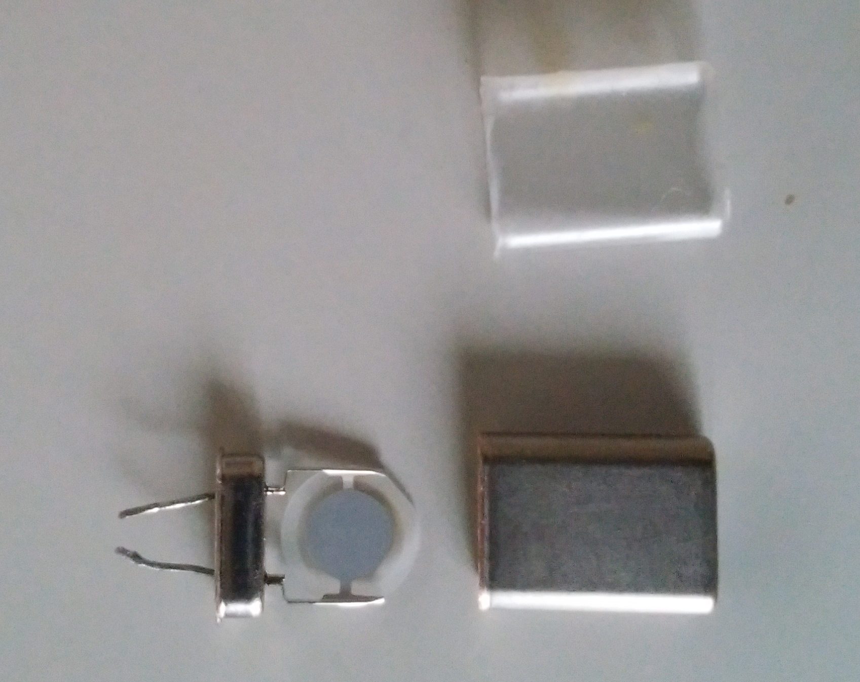
使うのはケースだけなので、でっぱり部分をニッパーで削除して、必要に応じてやすりで削って、中身を取り出します。
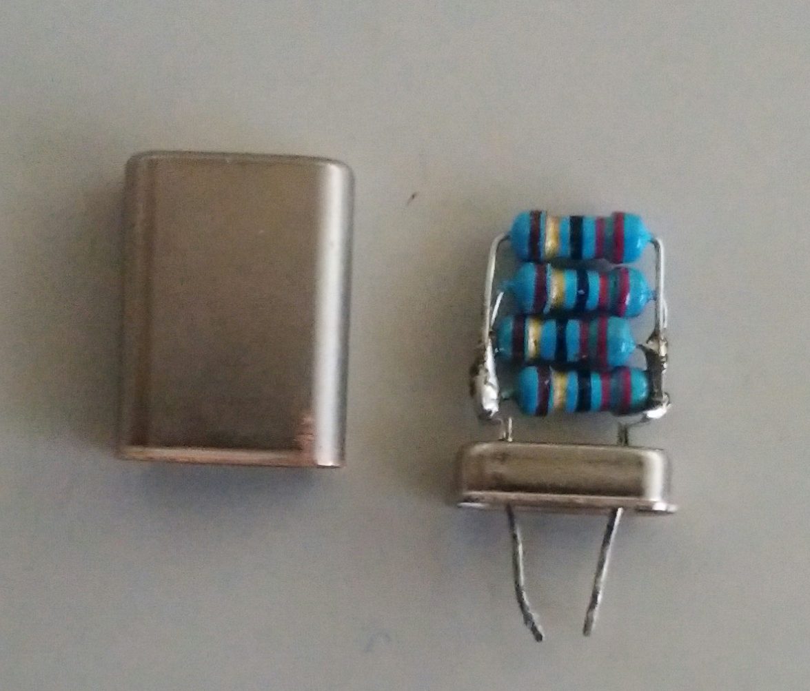
発熱体となる抵抗を取り付けます。
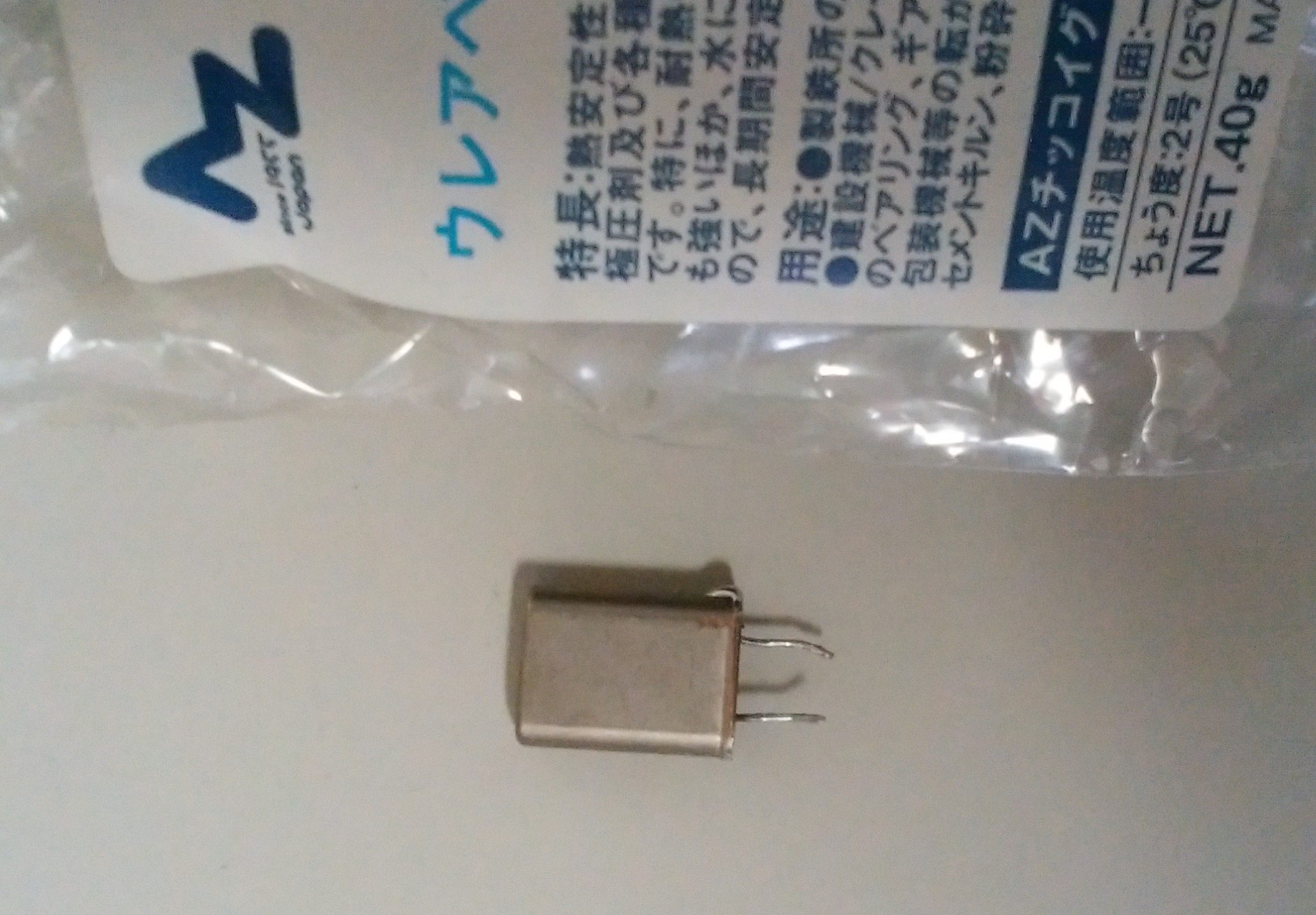
熱伝導性に優れたグリースを詰め込んで封印します。使用したのは、ホームセンターなどで売っている極圧グラファイトグリースです。絶縁性があり熱伝導性が高い優れもので、耐熱性も200℃と高く粘度も低めで密着度も良いので、やたら高いヒートシンク取り付け用のグリースの代わりにも使用できます。
このヒーターと温度センサーを水晶発振子を挟むように取り付け、Arduinoで温度制御します。
Arduinoのレギュレータの強化
消費電力を抑えめに作ってはいますが、Heaterを駆動するとなるとArduino標準のレギュレーターにはかなりの負担になり発熱も半端でなくなります。
かなりいい加減ですが、簡易的な放熱強化をしました。

接触したらまずいところに耐熱性のあるテープを貼って、クリップでつまんだだけです。
あと整流ダイオード(逆差し防止ダイオード)も発熱するので、その裏側に小型のヒートシンク
かなり手抜きですが、これでもそれなりに機能をはたしてくれています。
外気温の影響を少なくする
ヒーターと温度計測用センサーを水晶発振子に貼り付けただけでは、外気温の影響がかなり大きいので、オシレータが乗っているシールドを保温材でくるみます。

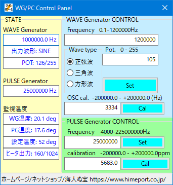
Si5351Aクロックジェネレータ + AD9833 DDS信号発生器 制御用Arduinoスケッチ
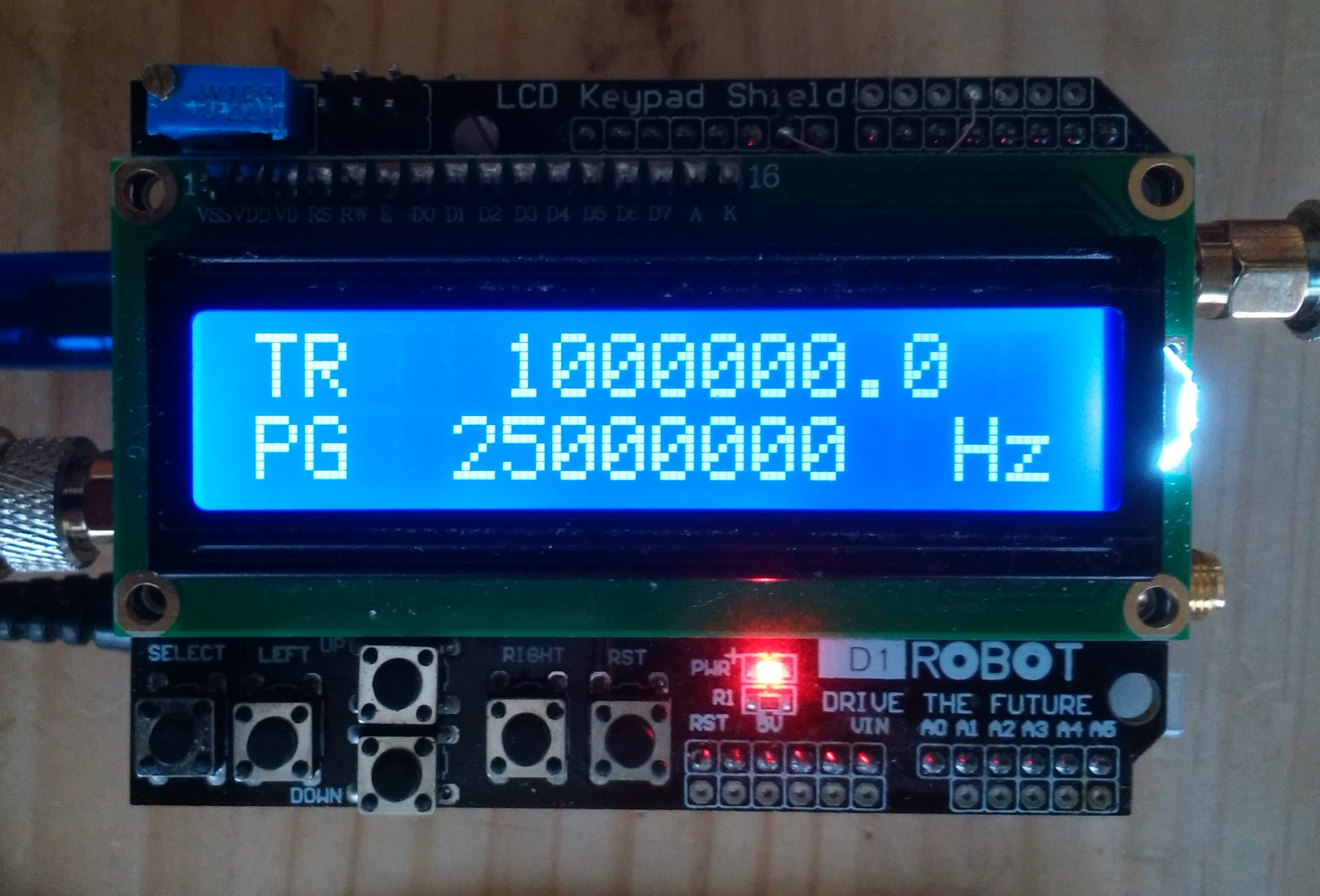
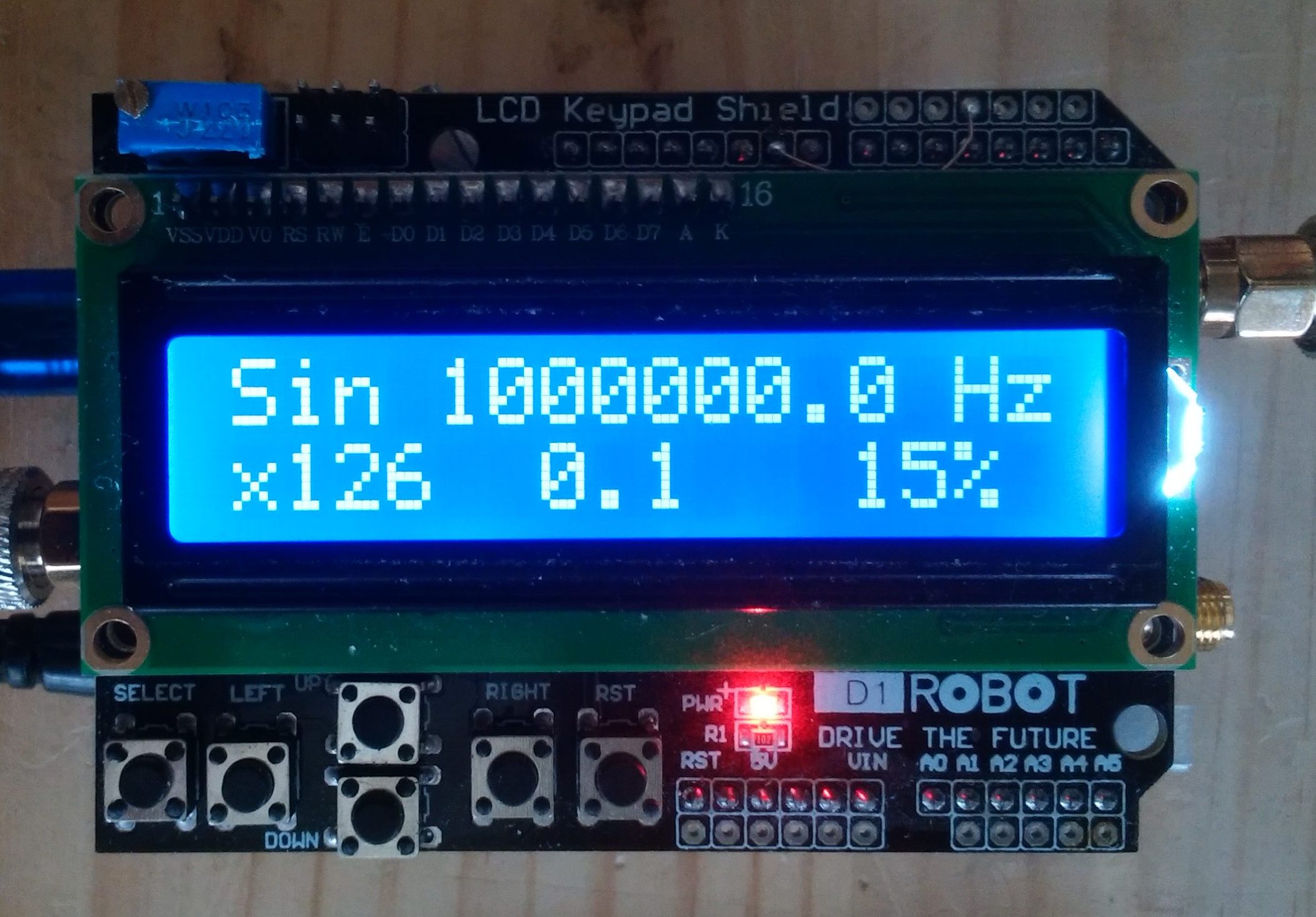
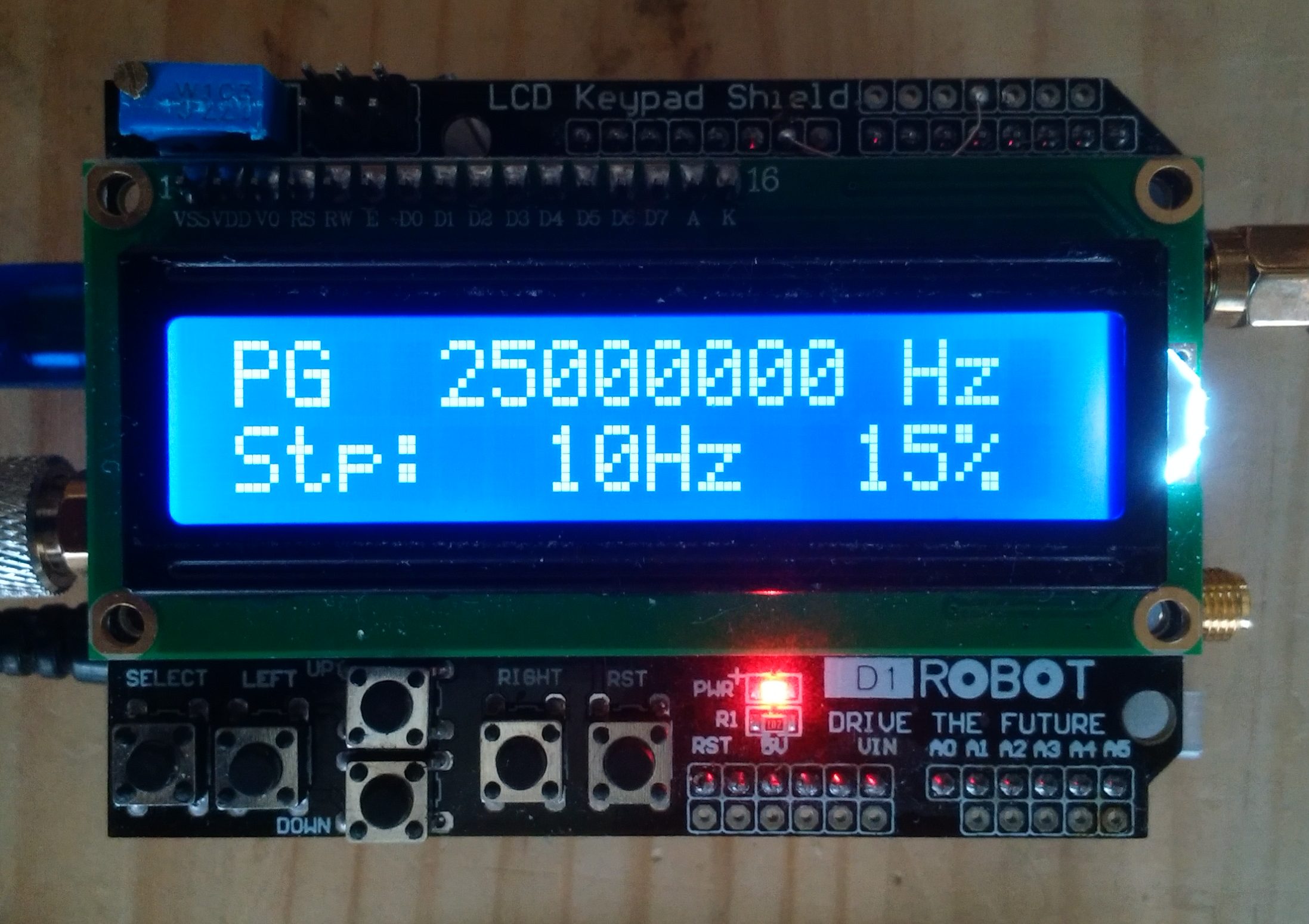
パネルの5つのスイッチで必要な操作はすべてできるように作ってあります。
/**************************************************************************/ //v.0.1 10.10.2018 Frequency generator 1.5k...200MHz . JrDrg //v.0.1c 10.14.2018 + OSC calibration //v.0.2c 10.15.2018 PLL clock Improvement + new Algorithm //v.0.3 10.16.2018 ch2 10MHz fix //v.0.3d 10.24.2018 Tuning、 bugFix //v.0.4 10.24.2018 +AD9833 WaveGen (DDS)1-1.2MHz Practical use:-800kHz //v.0.88 11.03.2018 High precision(8bits->16bits) temperature control //v.0.89 11.03.2018 Change WG Panel+Button,+ Step operation //v.0.91 11.05.2018 add Sirial cntrol //v.0.92 11.06.2018 freq High precision : float -> long //v.0.94 11.08.2018 キャリブレーション方法の変更 //v.0.95 11.08.2018 si5351ライブラリの変更 PG:4k-225MHz /**************************************************************************/ #include <Wire.h> #include <SPI.h> #include <LiquidCrystal.h> #include <avr/io.h> #include <avr/wdt.h> /* si5351.h - Si5351 library for Arduino https://github.com/etherkit/Si5351Arduino */ #include <si5351.h> Si5351 si5351; //◆ Siral Debug 0:off 1:on 1<:manual check byte debug = 0; int SGmenu = 0;//0:Top 1:Pulse 2:Wave // select SW long Push > 5s => Top menu const int loopwait = 100; int chrcnt = 0; //Sirial command I/F Chra count uint8_t input[33]; int cmdphase = 0; //Sirial command phase long Num; int64_t NumL; // heater setup #define ht_pin 9 // pin 3 -> 9(16bits PB1) // Temp ctrl start time int initwait = 3000; // about 5minits [3000*loopwait] // Temp Transient characteristics const int invtimerlimit_base = 5000; // about 5s Temp ctrl interval int invtimerlimit = invtimerlimit_base; int invtimer = 0; int temploop = 0; int anlg1; int anlg2; //WaveGen OSC Temp float temp; float temp2; float temp2_old = 0; float dtemp; //◆ Target oven temp const int terget_temp_base = 52; //simple oven temp int terget_temp = terget_temp_base; int heater = 160; //heater init set 150-205 <0-1023> /* Key setup */ int lcd_key = 0; int adc_key_in = 0; int adc_key_in2 = 0; #define btnRIGHT 0 #define btnUP 1 #define btnDOWN 2 #define btnLEFT 3 #define btnSELECT 4 #define btnNONE 5 #define waveSELECT 6 const int lcdLED = 10; LiquidCrystal lcd(8, 3, 4, 5, 6, 7);//9->3 /*AD9833 WaveGen (DDS) Setup*/ const int SINE = 0x2000; // Define AD9833's waveform register value. const int SQUARE = 0x2028; // When we update the frequency, we need to const int TRIANGLE = 0x2002; // define the waveform when we end writing. int wave = 0; int waveType = SINE; //◆ Set wave generator initial frequency. unsigned long freq10 = 10000000; //freq * 10 const long freqTRmax = 1200000; // max 1.2MHz(Practical 1MHz) const long freqSQmax = 1200000; // max 1.2MHz(Practical 500kHz) const long freqSImax = 6000000; // max 5MHz(Practical 5MHz) unsigned long freqMAX = freqSImax; //◆ Wave generator OSC clock const long refFreq_base = 250003334; // On-board crystal reference frequency 25000318.4*10 unsigned long refFreq10 = refFreq_base; const int FSYNC = 2; // Standard SPI pins for the AD9833 waveform generator. 10=>2 const int CLK = 13; // CLK and DATA pins are shared with the TFT display. const int DATA = 11; const int CS = A3; //MCP41010 potentiometer 9=>A3(17) // digital pot values for differant wave forms to maintain constant output level(1-255) const int TRPOTmax = 220; const int SQPOTmax = 29; const int SIPOTmax = 220; int TRPOT = 126; int SQPOT = 15; int SIPOT = 126; int exPOTmax = SIPOTmax; int exPOT = SIPOT; // potmode for determining digipot setting byte potVal = exPOT; int adc_key_wait = 40; int read_LCD_buttons() { // take measures to chattering adc_key_in = analogRead(0); delay(adc_key_wait); adc_key_in2 = analogRead(0); if (abs(adc_key_in - adc_key_in2) > 2) return btnNONE; // For V1.1 us this threshold if (adc_key_in > 1000) return btnNONE; // We make this the 1st option for speed reasons since it will be the most likely result // For V1.1 us this threshold if (adc_key_in < 50) return btnRIGHT; if (adc_key_in < 250) return btnUP; if (adc_key_in < 350) return btnDOWN; if (adc_key_in < 550) return btnLEFT; if (adc_key_in < 850) return btnSELECT; return btnNONE; } void wait_btnNONE() { lcd_key = read_LCD_buttons(); // read the buttons while (lcd_key != btnNONE) { lcd_key = read_LCD_buttons(); // read the buttons } } //◆ Pulse Gen OSC Normal: oscf=25000000 const long oscf_base = 25000000 ; //base OSC frequency const long osc_devi_stnd = 56990 ; // (偏差/10MHz) ppm long pcal_devi = osc_devi_stnd ; //Ref Volt float Vref; //◆ Pulse Generator Initial Output Clock Freq uint64_t outF = 25000000 ;// initial frequency in Hz const long outF2 = 10000000; //ch2: Fix frequency uint32_t stpx; //freq freq step size uint8_t changed_f = 1; char msg10[10]; char s8[8]; /**************************************/ /* Calc Pram & Displays the frequency */ /**************************************/ void count_frequency() { /**************************************/ /* Displays the PG frequency */ /**************************************/ lcd.clear(); lcd.setCursor(0, 0); char msg[12]; char s[9]; char msg4[5]; char s4[2]; sprintf(msg, "PG %s", dtostrf((outF / 10), 8, 0, s)); sprintf(msg4, "%s Hz", dtostrf((outF % 10), 1, 0, s4)); lcd.print(msg); lcd.print(msg4); display_stpx(); } /**************************************/ /* Display the frequency change step */ /**************************************/ void display_stpx() { lcd.setCursor(0, 1); lcd.print("Stp:"); switch (stpx) { case 10: lcd.print(" 10"); break; case 100: lcd.print(" 100"); break; case 1000: lcd.print(" 1k"); break; case 10000: lcd.print(" 10k"); break; case 100000: lcd.print("100k"); break; case 1000000: lcd.print(" 1M"); break; case 10000000: lcd.print(" 10M"); break; } lcd.print("Hz "); } void setup_PGfreq0() { //◆ display setup param if (changed_f > 0) { count_frequency(); uint64_t outF_100 = outF; outF_100 = outF_100 * 100; si5351.output_enable(SI5351_CLK0, 0); delay(10); si5351.set_correction(pcal_devi, SI5351_PLL_INPUT_XO); si5351.set_ms_source(SI5351_CLK0, SI5351_PLLA); si5351.set_freq(outF_100, SI5351_CLK0); si5351.drive_strength(SI5351_CLK0, SI5351_DRIVE_8MA); si5351.output_enable(SI5351_CLK0, 1); si5351.update_status(); } } void setup_PGfreq2() { uint64_t outF2_100 = outF2; outF2_100 = outF2_100 * 100; si5351.output_enable(SI5351_CLK2, 0); delay(10); si5351.set_correction(pcal_devi, SI5351_PLL_INPUT_XO); si5351.set_ms_source(SI5351_CLK2, SI5351_PLLB); si5351.set_freq(outF2_100, SI5351_CLK2); si5351.drive_strength(SI5351_CLK2, SI5351_DRIVE_8MA); si5351.output_enable(SI5351_CLK2, 1); si5351.update_status(); } /**************************************/ /* Display the WG frequency */ /**************************************/ void display_WGfreq() { lcd.setCursor(0, 0); char msg[19]; char s[13]; // sprintf(msg, "WG %s Hz", dtostrf(freq, 9, 1, s)); switch (waveType) { case SINE: { sprintf(msg, "Sin %s Hz", dtostrf((freq10 / 10.0), 9, 1, s)); break; } case TRIANGLE: { sprintf(msg, "Tri %s Hz", dtostrf((freq10 / 10.0), 9, 1, s)); break; } case SQUARE: { sprintf(msg, "Squ %s Hz", dtostrf((freq10 / 10.0), 9, 1, s)); break; } } lcd.print(msg); } void display_WG() { lcd.clear(); display_WGfreq(); char msg5[5]; char ss[4]; lcd.setCursor(0, 1); sprintf(msg5, "x%s ", dtostrf(exPOT, 3, 0, ss)); lcd.print(msg5); lcd.setCursor(5, 1); switch (stpx) //WG stpx=step*10 { case 1: lcd.print(" 0.1"); break; case 100: lcd.print("10Hz"); break; case 10000: lcd.print("1kHz"); break; case 1000000: lcd.print("100k"); } } // AD9833 documentation advises a 'Reset' on first applying power. void AD9833reset() { WriteRegister(0x100); // Write '1' to AD9833 Control register bit D8. delay(10); } // Set the frequency and waveform registers in the AD9833. void AD9833setFrequency(unsigned long frequency10, int Waveform) { unsigned long FreqWord = ((frequency10 * pow(2, 28)) / refFreq10 ); int MSB = (int)((FreqWord & 0xFFFC000) >> 14); //Only lower 14 bits are used for data int LSB = (int)(FreqWord & 0x3FFF); //Set control bits 15 ande 14 to 0 and 1, respectively, for frequency register 0 LSB |= 0x4000; MSB |= 0x4000; WriteRegister(0x2100); WriteRegister(LSB); // Write lower 16 bits to AD9833 registers WriteRegister(MSB); // Write upper 16 bits to AD9833 registers. WriteRegister(0xC000); // Phase register WriteRegister(Waveform); // Exit & Reset to SINE, SQUARE or TRIANGLE } void WriteRegister(int dat) { // Display and AD9833 use different SPI MODES so it has to be set for the AD9833 here. SPI.setDataMode(SPI_MODE2); digitalWrite(FSYNC, LOW); // Set FSYNC low before writing to AD9833 registers delayMicroseconds(10); // Give AD9833 time to get ready to receive data. SPI.transfer(highByte(dat)); // Each AD9833 register is 32 bits wide and each 16 SPI.transfer(lowByte(dat)); // bits has to be transferred as 2 x 8-bit bytes. digitalWrite(FSYNC, HIGH); //Write done. Set FSYNC high } void MCP41010Write(byte value) { // Note that the integer vale passed to this subroutine // is cast to a byte digitalWrite(CS, LOW); delayMicroseconds(10); SPI.transfer(B00010001); // This tells the chip to set the pot SPI.transfer(value); // This tells it the pot position delay (1); digitalWrite(CS, HIGH); } /* 電源電圧の読出 2014/7/19 ラジオペンチ http://radiopench.blog96.fc2.com/ */ float cpuVcc() { // 電源電圧(AVCC)測定関数 long sum = 0; adcSetup(0x4E); // Vref=AVcc, input=internal1.1V for (int n = 0; n < 10; n++) { sum = sum + adc(); // adcの値を読んで積分 } return (1.1 * 10240.0) / sum; // 電圧を計算して戻り値にする } void adcSetup(byte data) { // ADコンバーターの設定 ADMUX = data; // ADC Multiplexer Select Reg. ADCSRA |= ( 1 << ADEN); // ADC イネーブル ADCSRA |= 0x07; // AD変換クロック CK/128 delay(10); // 安定するまで待つ } unsigned int adc() { // ADCの値を読む unsigned int dL, dH; ADCSRA |= ( 1 << ADSC); // AD変換開始 while (ADCSRA & ( 1 << ADSC) ) { // 変換完了待ち } dL = ADCL; // LSB側読み出し dH = ADCH; // MSB側 return dL | (dH << 8); // 10ビットに合成した値を返す } // Array to Numeric conversion int64_t covNum() { // 入力値の10倍を返す。小数点以下は1桁以内限定 uint8_t asc; uint32_t ascN; int64_t NumL = 0; for (int8_t i = 0 ; i < chrcnt ; i++) { asc = input[i]; if ((asc != '.') && (asc != '-') && (asc != ' ')) { if ((asc >= 0x30) && (asc < 0x3A)) { ascN = (uint32_t)(asc - 0x30); NumL = (uint32_t)(NumL * 10ULL); NumL = (uint32_t)(NumL + ascN); } else NumL = 0; } } if (input[chrcnt - 2] != '.') NumL = (uint32_t)(NumL * 10UL); if (input[0] == '-') NumL = -1 * NumL; return (int64_t)NumL; } // Software reset void software_reset() { wdt_disable(); wdt_enable(WDTO_15MS); while (1) {} } void setup(void) { lcd.begin(16, 2); // PG Wire.begin(); // WG AD9833 SPI.begin(); Serial.begin(115200); delay(1000); Serial.println("******************"); Serial.println("* 1-1.2MHz WG *"); Serial.println("* 4k-220MHz PG *"); Serial.println("******************"); Serial.println("hello"); if (debug) { Serial.print("* Debug mode :"); Serial.print(debug); Serial.println(" *"); Serial.print("* SGmenu :"); Serial.print(SGmenu); Serial.println(" *"); Serial.println(""); } /* 電源電圧の読出 2014/7/19 ラジオペンチ http://radiopench.blog96.fc2.com/ */ Vref = cpuVcc(); // 電源電圧測定 // Heater pin pinMode(ht_pin, OUTPUT); //10bit高速PWM TCCR1A = 0b10000011; TCCR1B = 0b00001001; OCR1A = (unsigned int)( 1023 * (heater / 1023.0)); // PORTB = 0b00000010; //pul up pinMode(lcdLED, OUTPUT); // Startting Tittle lcd.setCursor(0, 0); // lcd.print("* WG: 0.1-1.2MHz*"); lcd.print("WG-1.2M//PG-200M"); lcd.setCursor(0, 1); // lcd.print("* PG: 4k-225MHz *"); lcd.print("18.1189 by JrDrg"); // pulse gen setup init clock // initialize the Si5351 bool i2c_found; i2c_found = si5351.init(SI5351_CRYSTAL_LOAD_10PF, 0 , 0 ); if (!i2c_found) { lcd.setCursor(0, 1); lcd.print(" PG clockgen error"); while (1); } si5351.reset(); delay(500); si5351.init(SI5351_CRYSTAL_LOAD_10PF, 0 , 0 ); /* set_correction(int32_t corr, enum si5351_pll_input ref_osc) corr - Correction factor in ppb ref_osc - Desired reference oscillator (use the si5351_pll_input enum) ref_osc - Desired reference oscillator 0: crystal oscillator (XO) 1: external clock input (CLKIN) */ changed_f = 1; /* Enable the clocks & Set Freq */ setup_PGfreq0(); setup_PGfreq2(); // Wave generator Startup pinMode (CS, OUTPUT); pinMode (FSYNC, OUTPUT); AD9833reset(); // Reset AD9833 module after power-up. delay(500); AD9833setFrequency(freq10, waveType); // Set the frequency and wave type delay(5); MCP41010Write (potVal); //Set Potentionmeter if (debug) { Serial.print(" potVal :"); Serial.println(potVal); } // temp dummy read anlg1 = analogRead(1) ; anlg2 = analogRead(2) ; delay(3000); //3seconds anlg2 = 0; for (int i = 1; i <= 20; i++) { anlg2 = anlg2 + analogRead(2) ; delay(5); } anlg2 = anlg2 / 20; temp2_old = ((Vref * anlg2) / 1024 / 2.907) * 100 - 60 ; } void loop(void) { switch (SGmenu) { case 0: { //★★ Top Menu // SGmenu = 1;//0:Top 1:Pulse 2:Wave // select SW long Push > 5s => Top menu // lcd.clear(); lcd.setCursor(0, 0); char msg[19]; char s[13]; switch (waveType) { case SINE: { sprintf(msg, "SI %s ", dtostrf(freq10 / 10.0, 9, 1, s)); break; } case TRIANGLE: { sprintf(msg, "TR %s ", dtostrf(freq10 / 10.0, 9, 1, s)); break; } case SQUARE: { sprintf(msg, "SQ %s ", dtostrf(freq10 / 10.0, 9, 1, s)); break; } } lcd.print(msg); lcd.setCursor(0, 1); char msg4[5]; char s4[2]; sprintf(msg, "PG %s", dtostrf((outF / 10), 8, 0, s)); sprintf(msg4, "%s Hz", dtostrf((outF % 10), 1, 0, s4)); lcd.print(msg); lcd.print(msg4); // sprintf(msg, "PG %s Hz", dtostrf(outF, 9, 0, s)); // lcd.print(msg); lcd_key = read_LCD_buttons(); // read the buttons switch (lcd_key) // depending on which button was pushed, we perform an action { case btnUP: { SGmenu = 2; lcd.setCursor(0, 1); changed_f = 1; stpx = 1; lcd.print(" "); lcd.setCursor(14, 0); lcd.print("Hz"); wait_btnNONE(); break; } case btnDOWN: { SGmenu = 1; stpx = 10; lcd.setCursor(0, 0); lcd.print(" "); changed_f = 1; wait_btnNONE(); break; } } } case 1: { //★★ PULSE GENERATER /**************************************/ /* Change the frequency */ /* btnUP Increment */ /* btnDOWN Decrement */ /* btnRIGHT Increment Tweak */ /* btnLEFT Decrement Tweak */ /**************************************/ lcd_key = read_LCD_buttons(); // read the buttons switch (lcd_key) // depending on which button was pushed, we perform an action { case btnUP: { outF += stpx; changed_f = 1; break; } case btnDOWN: { outF -= stpx; changed_f = 1; break; } case btnRIGHT: { outF += 1; changed_f = 1; break; } case btnLEFT: { outF -= 1; changed_f = 1; break; } } // btnSELECT frequency step Renge if (lcd_key == btnSELECT) // check long push (Return SGmenu) { digitalWrite(lcdLED, HIGH); // check btnSELECT > 5s for (int i = 1; i <= int(2500 / adc_key_wait); i++) { lcd_key = read_LCD_buttons(); // read the buttons if (lcd_key != btnSELECT) break; delay(adc_key_wait); } if (lcd_key != btnSELECT) lcd_key = btnSELECT; else SGmenu = 0; } if (SGmenu != 1) break; if (lcd_key == btnSELECT) { switch (stpx) { case 10: stpx = 100; break; case 100: stpx = 1000; break; case 1000: stpx = 10000; break; case 10000: stpx = 100000; break; case 100000: stpx = 1000000; break; case 1000000: stpx = 10000000; break; case 10000000: stpx = 10; break; } display_stpx(); } if ((changed_f > 0) && !(debug > 1)) { // check over renge if (outF > 225000000) outF = 4000; if (outF < 4000) outF = 225000000; if (outF < 0) outF = 225000000; setup_PGfreq0(); changed_f = 0; } break; } case 2: { //★★ Wave Generator /*************************************/ /* Change the frequency & potention */ /* btnUP freq Increment */ /* btnDOWN freq Decrement */ /* btnRIGHT pot Increment */ /* btnLEFT pot Decrement */ /* btnSELECT Change Wave */ /*************************************/ lcd_key = read_LCD_buttons(); // read the buttons while ((lcd_key == btnUP) || (lcd_key == btnDOWN)) { switch (lcd_key) // depending on which button was pushed, we perform an action { case btnUP: { freq10 += stpx; break; } case btnDOWN: { freq10 -= stpx; break; } } changed_f = 1; // check over renge if (freq10 > freqMAX)freq10 = 1; else if (freq10 <= 0)freq10 = freqMAX * 10; // if (freq > 1000000) freq = long(freq / 10) * 10; AD9833setFrequency(freq10, waveType); // Set the frequency and wave type display_WGfreq(); changed_f = 0; delay(adc_key_wait); lcd_key = read_LCD_buttons(); // read the buttons } switch (lcd_key) // depending on which button was pushed, we perform an action { case btnRIGHT: { exPOT += 1; changed_f = 1; break; } case btnLEFT: { exPOT -= 1; changed_f = 1; break; } } // check over renge if (changed_f > 0){ if (freq10 > freqMAX * 10)freq10 = 1; else if (freq10 <= 0)freq10 = freqMAX * 10; if (exPOT > exPOTmax)exPOT = 0 ; else if (exPOT < 0)exPOT = exPOTmax; potVal = exPOT; MCP41010Write (potVal); //Set Potentionmeter display_WG(); changed_f = 0; } // btnSELECT WaveType if (lcd_key == btnSELECT) // check long push (Return SGmenu) { uint32_t t_cont; digitalWrite(lcdLED, HIGH); // check btnSELECT > 5s for (t_cont = 1; t_cont <= int(2500 / adc_key_wait); t_cont++) { lcd_key = read_LCD_buttons(); // read the buttons if (lcd_key != btnSELECT) break; if (t_cont > int(2500 / adc_key_wait / 2)) { lcd.setCursor(0, 0); lcd.print("***"); } delay(adc_key_wait); } if (debug) { Serial.println(t_cont); } if (lcd_key != btnSELECT) { if (t_cont > int(2500 / adc_key_wait / 2))lcd_key = waveSELECT; else lcd_key = btnSELECT; } else { SGmenu = 0; break; } if (SGmenu !=0){ if (lcd_key == btnSELECT) { changed_f = 1; switch (stpx) { case 1: stpx = 100; break; case 100: stpx = 10000; break; case 10000: stpx = 1000000; break; case 1000000: stpx = 1; } } if ((lcd_key == waveSELECT) && (freq10 <= freqSQmax * 10)) { //freqSQmax >> other max changed_f = 1; switch (waveType) { case SINE: { SIPOT = exPOT; waveType = TRIANGLE; freqMAX = freqTRmax; exPOTmax = TRPOTmax; exPOT = TRPOT; break; } case TRIANGLE: { TRPOT = exPOT; waveType = SQUARE; freqMAX = freqSQmax; exPOTmax = SQPOTmax; exPOT = SQPOT; break; } case SQUARE: { SQPOT = exPOT; waveType = SINE; freqMAX = freqSImax; exPOTmax = SIPOTmax; exPOT = SIPOT; break; } } AD9833setFrequency(freq10, waveType); // Set the frequency and wave type } } } if (SGmenu != 2) break; if (changed_f) { display_WG(); changed_f = 0; } break; } } /* heater control */ // get PG OSC temp anlg1 = 0; for (int i = 1; i <= 20; i++) { anlg1 = anlg1 + analogRead(1) ; delay(5); } anlg1 = anlg1 / 20; temp = ((Vref * anlg1) / 1024) * 100 - 60 ; // get WG OSC temp2 anlg2 = 0; for (int i = 1; i <= 20; i++) { anlg2 = anlg2 + analogRead(2) ; delay(5); } anlg2 = anlg2 / 20; temp2 = ((Vref * anlg2) / 1024 / 2.907) * 100 - 60 ; // OpAmp gain: x2.907 if (abs(terget_temp - temp2 ) < 1)initwait = 0; // 設定温度に近い場合、温度制御を強制スタート if (initwait > 0) initwait -= 1; // Temp ctrl start waiting else { if ((terget_temp - temp2) < -0.8)invtimerlimit = invtimerlimit_base / 4; else invtimerlimit = invtimerlimit_base; if ((invtimer * loopwait) > invtimerlimit) { invtimer = 0; if (abs(terget_temp - temp2 ) <= 0.4) heater += 0; else if (((terget_temp - temp2 ) > 4) && (heater < 984 ) && (temp2 <= temp2_old)) { heater += 40; temploop = 0; } else if (((terget_temp - temp2 ) < -3) && (heater > 19 ) && (temp2 >= temp2_old)) { heater -= 20; temploop = 0; } else if (abs(temp2 - temp2_old) <= 0.4) { heater += 0; temploop += 1; if (temploop > 5) { temploop = 0; if ((terget_temp - temp2) > 0) heater += 1; else { if ((terget_temp - temp2) <= 2)heater -= 1; else heater -= 2; } } } else if (((terget_temp - temp2) > 0) && (heater < 1023) && (temp2 <= temp2_old)) { heater = heater += 1; temploop = 0; } else if (((terget_temp - temp2) < 0) && (heater > 0) && (temp2 >= temp2_old)) { heater -= 1; temploop = 0; } temp2_old = temp2; // set heater PWM Duty(heater/1023.0) OCR1A = (unsigned int)( 1023 * (heater / 1023.0)); } invtimer += 1; } if (debug) { Serial.print("** "); Serial.print(Vref); Serial.print("V "); Serial.print(initwait); Serial.print(" "); Serial.print(invtimer); Serial.print(" "); Serial.print(temploop); Serial.print(" "); Serial.print(heater); Serial.print(" "); Serial.print(temp2_old); Serial.print("℃ "); Serial.print(temp2); Serial.print("℃ "); Serial.print(temp); Serial.println("℃ "); } /* 温度が設定値に近づくとバックライトが点灯 温度が異常だとバックライトが点滅 温度がほぼ設定値になるまで、温度差を点滅表示 */ dtemp = temp2 - terget_temp ; if (abs(dtemp) < 0.8) digitalWrite(lcdLED, HIGH); else { if (dtemp < 5) { if ((initwait % 2) > 0) { digitalWrite(lcdLED, LOW); } else { digitalWrite(lcdLED, HIGH); } } else { // set heater PWM Duty 0% = Power down OCR1A = (unsigned int)( 1023 * (0 / 1023.0)); digitalWrite(lcdLED, LOW); } } if (SGmenu > 0) { temp = (temp2 + temp) / 2; char msgT[5]; char sT[5]; lcd.setCursor(11, 1); if (initwait > 0) { if ((initwait % 2) > 0) { lcd.print(" "); } else { sprintf(msgT, " %s0", dtostrf(dtemp, 2, 2, sT)); lcd.print(msgT); } } else { if (((invtimer % 2) > 0) && (abs(dtemp) > 0.4)) { lcd.print(" "); } else { sprintf(msgT, "%s", dtostrf(int(heater / 1023.0 * 100.0), 3, 0, sT)); lcd.print(msgT); lcd.print('%'); } } } //Sirial command I/F chrcnt /* cmdphase 1:w(WG) 5:<freq:0.1-1200000.0> 6:<POT:0-127> 7:i(sin) :r(tri) :q(squ) 2:p(PG) 10:<freq:1-205000000> 3:t(temp) 11:<Target_temp:40-55> 12:<heater:0-1023> 4:g(get) return status PG freq,WG freq,WG waveform,WG pot,temp2,temp,heater,target temp 13:c(WG calibration) 16:<+-freq/10:-500~+500> 14:C(PG calibration) 17:<+-freq/10:-500~+500> 18:r(reboot) 19:D(set Direct PG parameter) ....opt. 20:d(Dump Direct PG parameter) 21:h(hello) for Sirial Command Sync 0:No command [\]:end mark */ if (Serial.available()) { input[chrcnt] = Serial.read(); if (chrcnt > 32 || input[chrcnt] == '\\') { // chrcnt=chrcnt-1; // ignore last'Y' switch (cmdphase) { case 0: { switch (input[0]) { case 'h': { Serial.println("Hi! my Master (^^) "); cmdphase = 0; break; } case 'w': { Serial.println("WG"); cmdphase = 5; break; } case 'p': { Serial.println("PG"); cmdphase = 10; break; } case 't': { Serial.println("TEMP"); cmdphase = 11; break; } case 'g': { Serial.print("Status: "); Serial.print((uint32_t)outF); Serial.print(" "); Serial.print(freq10 / 10, DEC); Serial.print("."); Serial.print((freq10 % 10), DEC); Serial.print(" "); Serial.print(waveType); Serial.print(" "); Serial.print(exPOT); Serial.print(" "); Serial.print(temp2, 1); Serial.print(" "); Serial.print(temp, 1); Serial.print(" "); Serial.print(heater); Serial.print(" "); Serial.println(terget_temp,1); //Serial.print(" "); //Serial.print(refFreq10 / 10, DEC); Serial.print("."); Serial.print((refFreq10 % 10), DEC); //Serial.print(" "); //Serial.println( pcal_devi ); cmdphase = 0; break; } case 'c': { Serial.println("WG"); cmdphase = 16; break; } case 'C': { Serial.println("PG"); cmdphase = 17; break; } case 'r': { Serial.println("Rboot"); software_reset(); cmdphase = 0; break; } case 'D': { Serial.println("OPT"); cmdphase = 0; //19 break; } case 'd': { Serial.print("PG: "); si5351.update_status(); Serial.print("SYS_INIT: "); Serial.print(si5351.dev_status.SYS_INIT); Serial.print(" LOL_A: "); Serial.print(si5351.dev_status.LOL_A); Serial.print(" LOL_B: "); Serial.print(si5351.dev_status.LOL_B); Serial.print(" LOS: "); Serial.print(si5351.dev_status.LOS); Serial.print(" REVID: "); Serial.println(si5351.dev_status.REVID); cmdphase = 0; break; } default: { Serial.println("What? "); cmdphase = 0; break; } } break; } case 5: { Num = covNum(); Serial.println("WG2"); //Serial.print(Num / 10, DEC); Serial.print("."); Serial.println((Num % 10), DEC); if ((Num > 0) && (Num < 120000001)) { freq10 = Num; cmdphase = 6; changed_f = 0; } else { cmdphase = 0; } break; } case 6: { Num = covNum(); //Serial.print(Num / 10, DEC); Serial.println("WG3"); if ((Num >= 0) && (Num < 2550)) { exPOT = Num / 10; //Serial.println(exPOT); switch (waveType) { case SINE: { SIPOT = exPOT; break; } case TRIANGLE: { TRPOT = exPOT; break; } case SQUARE: { SQPOT = exPOT; break; } } } changed_f = 0; cmdphase = 7; break; } case 7: { Serial.println("WG4"); switch (input[0]) { case 'i': { waveType = SINE; changed_f = 1; break; } case 'r': { waveType = TRIANGLE; changed_f = 1; break; } case 'q': { waveType = SQUARE; changed_f = 1; break; } default: { changed_f = 0; break; } } if (changed_f = 1) { switch (waveType) { case TRIANGLE: { freqMAX = freqTRmax; exPOTmax = TRPOTmax; break; } case SQUARE: { freqMAX = freqSQmax; exPOTmax = SQPOTmax; break; } case SINE: { freqMAX = freqSImax; exPOTmax = SIPOTmax; break; } } AD9833setFrequency(freq10, waveType); // Set the frequency and wave type potVal = exPOT; //Serial.println(exPOT); MCP41010Write (potVal); //Set Potentionmeter display_WG(); changed_f = 0; cmdphase = 0; } break; } case 10: { NumL = (int64_t)covNum(); if ((NumL >= 40000) && (NumL <= 2250000000)) { outF = (int64_t)(NumL / 10); //Serial.print((uint32_t)outF); Serial.println("PG"); changed_f = 1; setup_PGfreq0(); changed_f = 0; } cmdphase = 0; break; } case 11: { Num = covNum(); if ((Num > 399) && (Num < 551)) { //Serial.print(Num / 10, DEC); Serial.println("TG"); terget_temp = Num / 10; cmdphase = 12; } else { cmdphase = 0; } break; } case 12: { Num = covNum(); if ((Num >= 0) && (Num < 10231)) { //Serial.print(Num / 10, DEC); Serial.println("HT"); heater = Num / 10; OCR1A = (unsigned int)( 1023 * (heater / 1023.0)); } cmdphase = 0; break; } case 16: { Num = covNum(); if ((Num > -2000001) && (Num < 2000001)) { Serial.println("WG"); //Serial.print(Num / 10, DEC); Serial.print("."); Serial.println(abs(Num % 10), DEC); refFreq10 = refFreq_base + Num; changed_f = 1; AD9833setFrequency(freq10, waveType); // Set the frequency and wave type display_WG(); changed_f = 0; } cmdphase = 0; break; } case 17: { Num = covNum(); if ((Num > -2000001) && (Num < 2000001)) { Serial.println("PG"); //Serial.print(Num / 10, DEC); Serial.print("."); Serial.println(abs(Num % 10), DEC); // クロック偏差をppmで入力。100MHzを偏差0.1まで計測、差分を設定 pcal_devi = Num; changed_f = 1; setup_PGfreq0(); setup_PGfreq2(); changed_f = 0; } cmdphase = 0; break; } default: { } cmdphase = 0; break; } chrcnt = 0; } else { chrcnt++; } } //loop delay delay(loopwait); } // END シリアルからのコマンドでも操作できるように作っていますので、WindowsからGUIで制御できるツールもついでに作成しちゃいました。 言語は、python 開発環境は、Visual Studio Codepythonは、本来は本格的なWeb用のプログラムなどを作成するものと思いますが、昔のBASIC的な位置付けでお手軽なプログラム言語としても使えます。 最近のPCはパワーが余っていますから、高速処理が苦手なインタプリタですが、中間言語で実行するのもあり、そこそこリアルタイムな処理も可能です。 また、マルチプラットホーム対応なのもGood、必要に応じて実行形式も作成可能です。
その他
温度制御にTC1を使用する為にLCDシールドの一部接続を変更しています。
居ないとは思いますが、もし参考にして作成される場合は掲載のスケッチのピン定義を事前に確認してください。
HW作成がいい加減なせいかもしれませんが、たまに波形が出ていない場合が見られ、ライブラリの使用方法か何かしら問題が潜んでいる可能性があります。(-_-;)
流用される場合は、注意してご利用ください。